

Application FAQ
1.How to choose the right CL of crystals?
1) Recommended CL of crystals by IC
2) Empirical CL Calculation
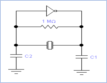
CL≈C1*C2/(C1+C2)+Cs
(HC-49S Series: Cs=6pF; SMD Series: Cs=3pF)
C1, C2: Ground Capacitance of Crystal
3) Matching Experiment
Test the output frequency with different CL to find out the right CL for the circuit.
2. How to Test the Negative Resistance?
The Measurement Method of Negative Resistance

The connection diagram of Negative Resistance Measurement
1). Put the adjustable resistance and the crystal in series;
2). Increase the resistance (Rt) from 0 to the one lead to the oscillation of the loop get stopped;
3). Measure the Rt when the oscillation of the loop just get stopped;
4). The negative resistance is: │-R│= Rt+Rr
Rr: the resistance of the crystal;
Rt: the test value of the adjustable resistance
5). The recommended negative resistance is:
│-R│> 10 Rr (unit: ohm)
1. The resistance range of the crystal will be decided based on this measurement;
2. This measurement will also tell the vibromotive ability, oscillation amplitude, circuit stability, redundancy of resistance, and the suitability of the capacitances (C1, C2)
Remark: the capacitance of oscilloprobe which monitor the output amplitude of the oscillation circuit should be less than 1pF.
How to connect the adjustable resistance in practice?
1. Put the crystal upright, just leave one pad connected to the PCB (for SMD3225, it's the PAD of crystal connected to crystal blank, and the one near to the IC output port, not the GND PAD);
2. One end of the adjustable resistance connects to the other PAD of crystal (for SMD3225, it's the other PAD of crystal connected to crystal blank), the other end of the adjustable resistance connects to the PAD (the one was connected to the PAD of crystal) on the PCB, then the crystal and the adjustable resistance are in series.
3. The cable connected to the adjustable resistance should be as short as possible.
4. The carbon film resistor is recommended.